Rail is by far one of the most efficient means of transportation. It is estimated that one train can move a ton of freight almost 500 miles on a single gallon of fuel. Today, Rail Companies are aggressively embracing environmental initiatives by investing in new technologies that further reduce their carbon footprint, energy use, and water consumption.
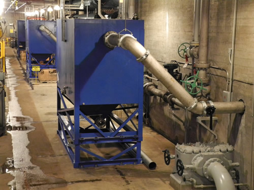
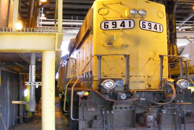
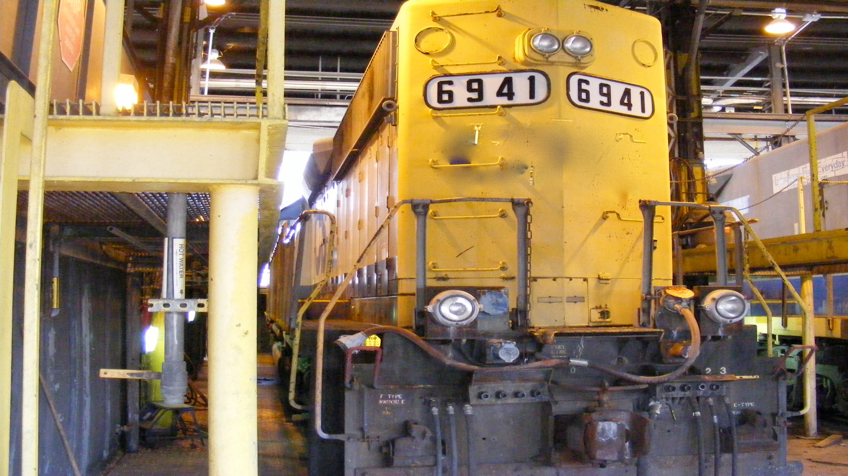
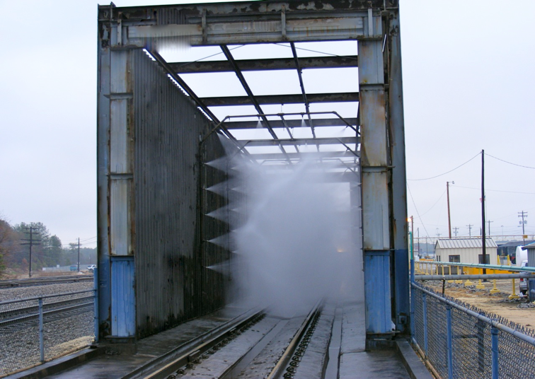
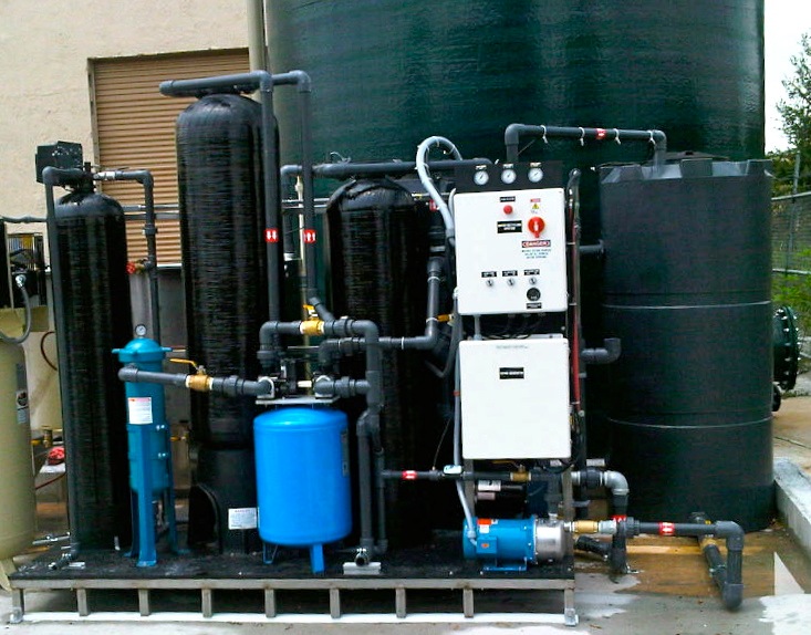
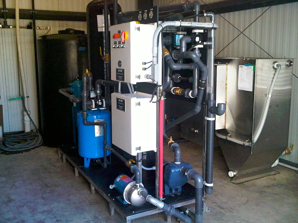
We can help rail companies keep the trains clean and in good working order AND help them reach their environmental goals. Engineered and manufactured for the locomotive industry, our Rail & Locomotive (RL Series) Systems are heavy-duty, multi-stage wash water reclaim systems which can be combined with our single or multi-stage wash and rinse arches for a complete wash system that uses a fraction of the water of other wash systems on the market.
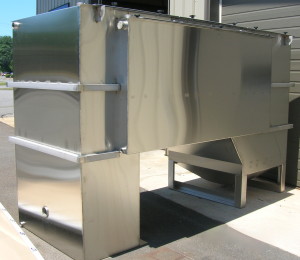
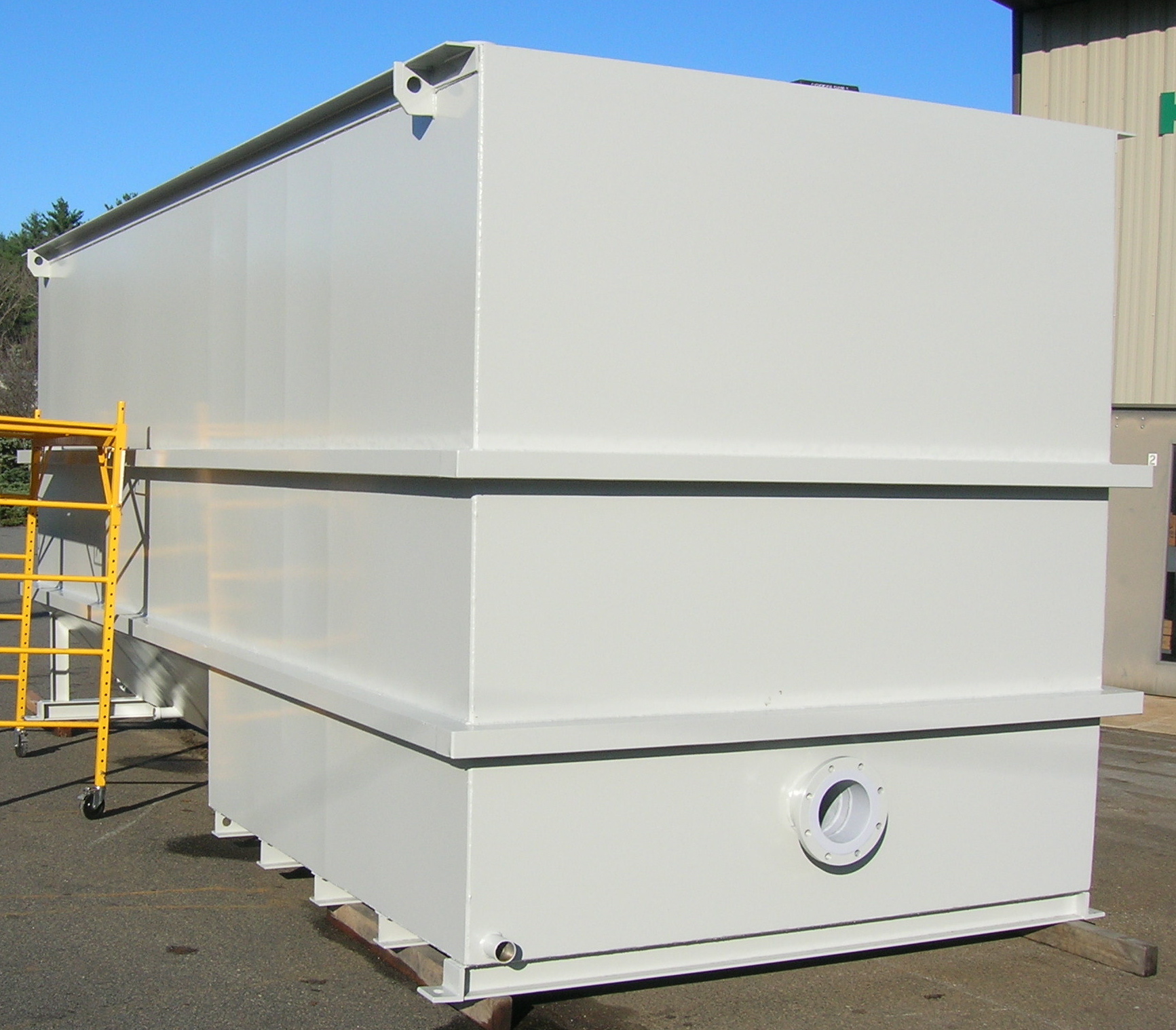
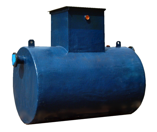
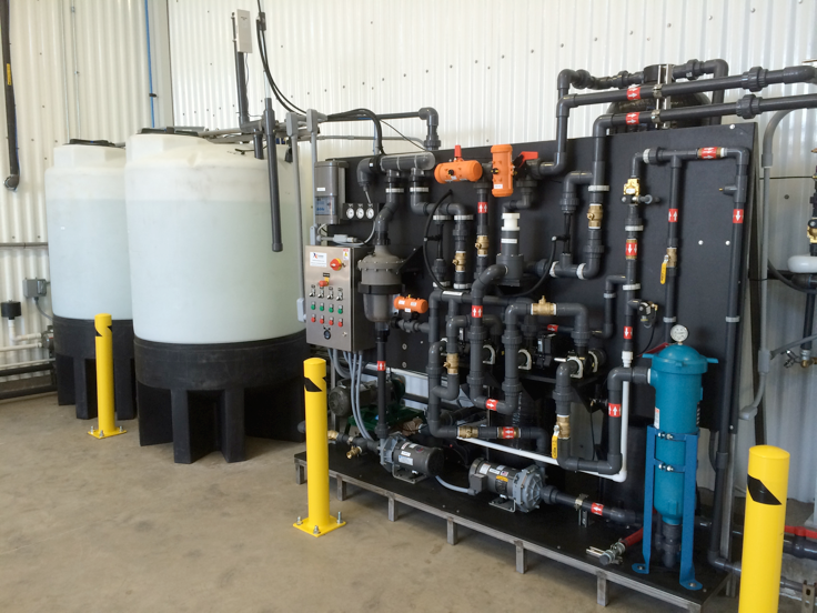
In the first stage our RL Systems, the water is processed through a stainless steel clarifier oil water separator which removes most suspended solids (TSS), essentially all settleable solids and all free and dispersed non-emulsified oils from the waste stream.
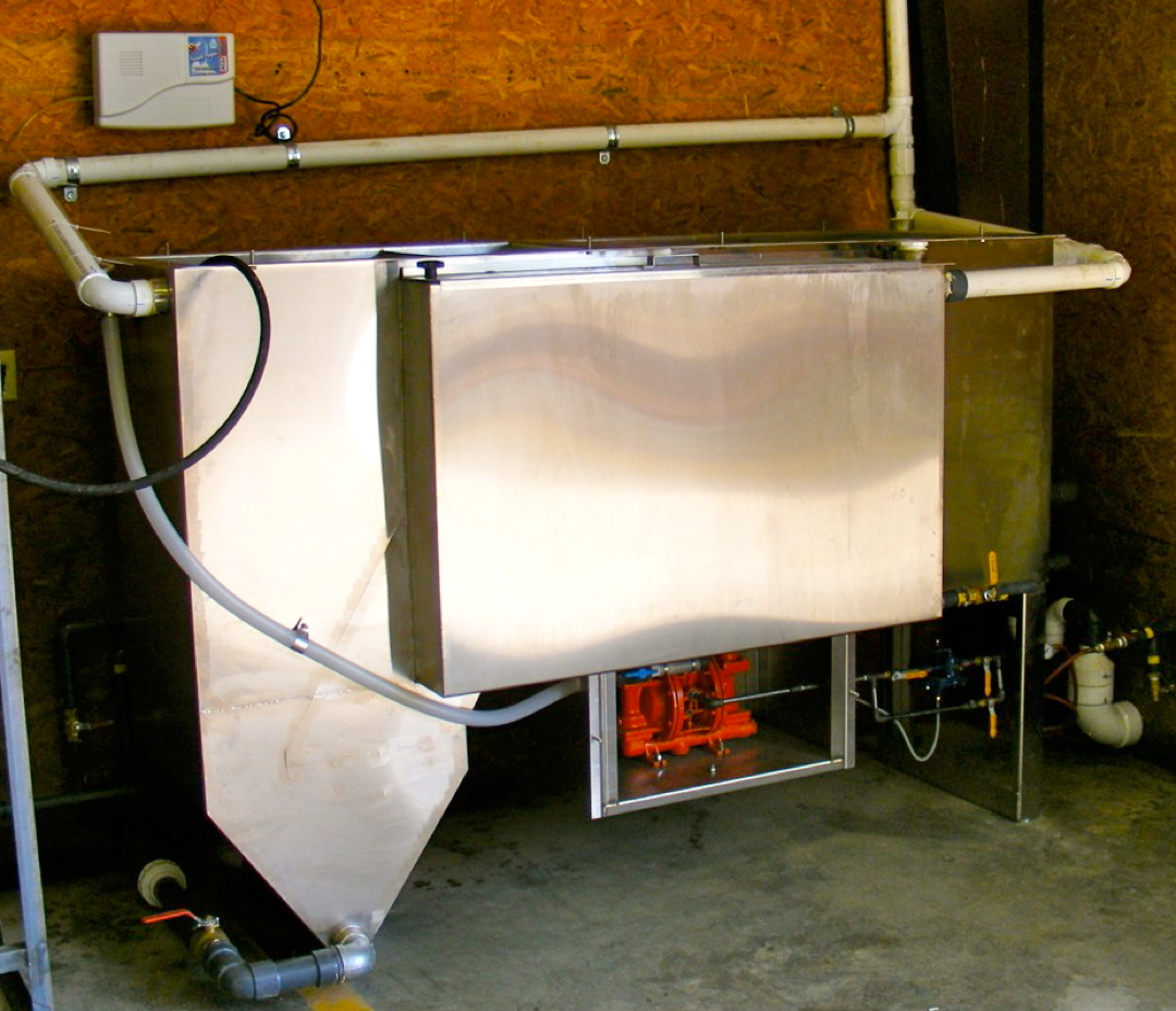
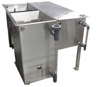
After the clarifier separator, the water is further processed for re-use by going through an extremely efficient filtration process utilizing fully automated solids filtration and a proprietary blended activated carbon (GAC) polishing filtration. Processed water passing through the system will be free of particles greater than 10 microns in size, substantially all emulsified oils, waxes and other volatile organic compounds.
RL SERIES STANDARD FEATURES:
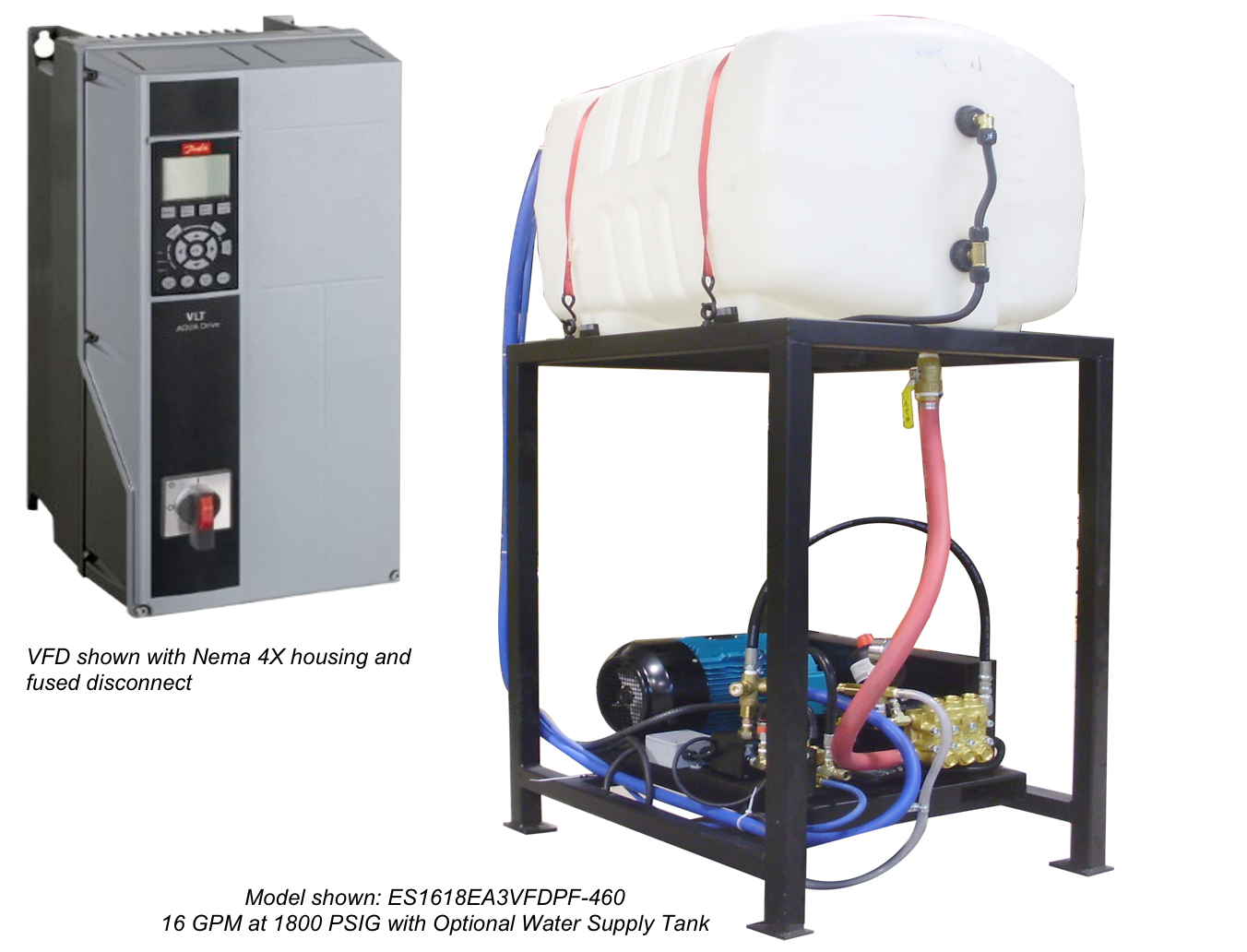
- High-Efficiency Pumps
- Corona Discharge Ozonation System
- Solids Handling & Separation
- TSS & FOG Reduction
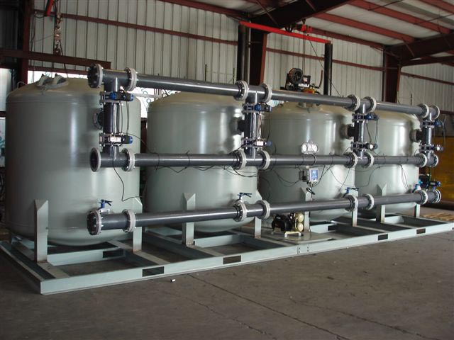
- Multi-Stage / Multi-Pass Filtration
- Pressurized Blended Carbon Polishing Filter
- Auto-Backwashing Filters
- Stainless Steel Construction
- NEMA 4X Control Panel with PLC controller
Depending on the location, many options are available to maximize the efficiency of the wastewater treatment system including:
OPTIONAL FEATURES:
- Wash & Rinse Arches
- Remote controls & switches
- SCADA and remote monitoring
- UL/CSA Listing
- Transportable equipment rooms
- Rain Diverter Systems
- Chemical/Acid/Salinity Resistant Pumps & Components
- ORP / pH control system
RL SERIES SYSTEM SPECIFICATIONS
| MODEL | RL-10/10 | RL-30/20 | RL-60/50 | RL-100 | RL-200* | |
|---|---|---|---|---|---|---|
| FLOW RATE, GPM | 1-10 | 1-30 | 10-60 | 30-100 | 60-200 | |
| COALESCING PLATE AREA, SF | 41 | 124 | 211 | 400 | 600 | |
| COALESCING MEDIA, CF | 4 | 8 | 24 | 48 | 96 | |
| APPROX. CLARIFIER SEPARATOR SIZE, FT (WxLxH) | 3 x 7 x 5 | 3.5 x 8 x 6 | 4 x 10 x 6 | 5 x 11 x 7 | 7 x 13 x 9 | |
| RECLAIM RE-CIRCULATION PUMP, HP | 1.5 | 3 | 3 | 5 | 5 | |
| RECLAIM RE-PRESSURIZATION PUMP, HP | 1 | 3 | 5 | 7.5 | 10 | |
| OZONE SYSTEM | Up to 32 grams of ozone per hour | |||||
| RECLAIM CONTROL SYSTEM | PLC, Automatic, Manual or Off | |||||
| RECLAIM PUMP FRAME SIZE, FT (WxL) (TANKS ADDITIONAL) |
3 X 6 | 3 x 8 | ||||
| POWER REQUIREMENTS | 208 / 240 V 1 ph or 208 / 240 / 480 V 3 ph | |||||
| * LARGER CAPACITY SYSTEMS (500-1500 GPM) ARE AVAILABLE | ||||||


 TREATMENT SYSTEMS")