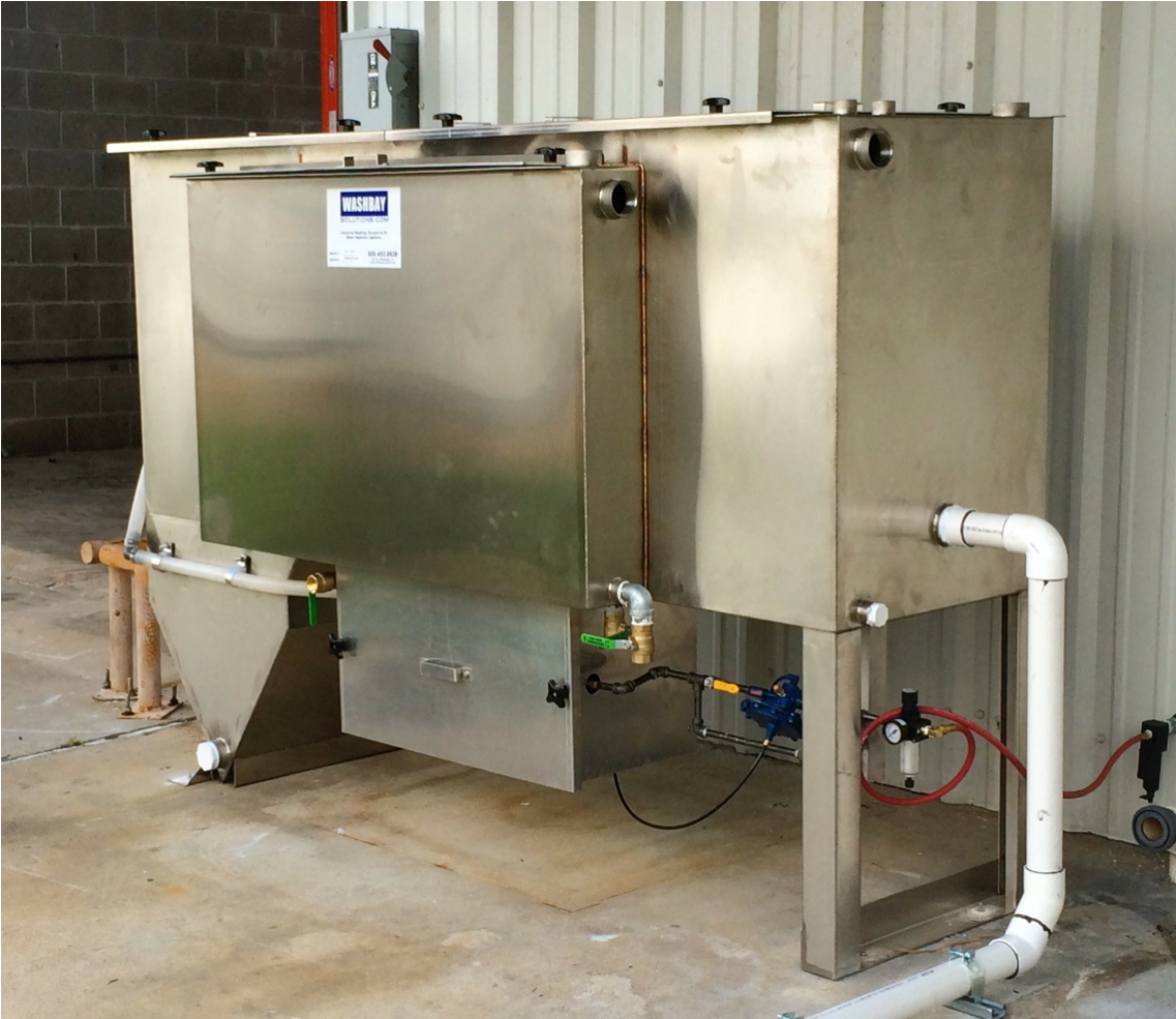
FABRICATION: The clarifier/separator is a special purpose prefabricated inclined plate and parallel corrugated plate, rectangular, gravity displacement, type unit. The clarifier/separator shall be comprised of a tank containing an inlet compartment, sludge chamber, a separation compartment, and clean water outlet chamber.
TANK: The tank shall be a single wall construction of 11 gauge stainless steel conforming to ASTM A240, type 304 stainless steel. Welding will be in accordance with AWS D1.1 to provide a watertight tank that will not warp or deform under load.
PIPE CONNECTIONS: All pipe connections 3” and smaller are FNPT couplings. All connections 4“ and larger are flat face flanges with ANSI 150 pound standard bolt circle.
LIFTING LUGS: The tank shall be provided with properly sized lifting lugs for handling and installation.
COVERS: The tank will be provided with vapor tight covers for vapor control. Gas vents and suitable access openings to each compartment will be provided. The covers shall be constructed of marine grade aluminum and will be fastened in place. A gasket shall be provided for vapor tightness. 3/8-16 bolts and threaded knobs will be provided for cover attachment.
INLET COMPARTMENT & INCLINED PLATES: The inlet chamber shall be comprised of a non-clog diffuser to distribute the flow across the width of the chamber. The inlet compartment shall be of sufficient volume to effectively reduce influent suspended solids, dissipate energy and begin separation. The inclined plates will sit elevated on top of a sludge chamber. As the water moves upwards the suspended particles have their upwards velocity interrupted by the inclined plates. These particles drop down and slide down the inclined plate and join larger previously settled particles in sludge hopper. The sludge compartment will be provided to retain settleable solids.
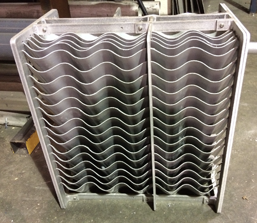
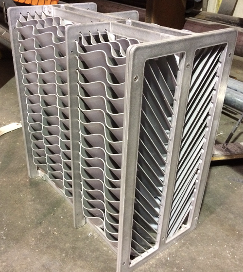
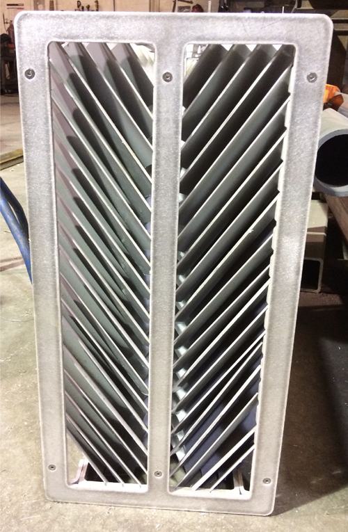
SEPARATION CHAMBER: The oil separation chamber shall contain HD Q-PAC Coalescing Media containing a minimum of 132 square feet per cubic foot of effective coalescing surface area. The medias needle like elements (plates) shall be at 90 degrees to the horizontal or longitudinal axis of the separator. Spacing between these elements shall be spaced 3/16” apart for the removal of a minimum of 99.9% of free droplets 20 micron in size or greater. The elements are positioned to create an angle of repose of 90 degrees to facilitate the removal of solids that may tend to build up on the coalescing surfaces, which would increase velocities to the point of discharging an unacceptable effluent.
Laminar flow with a Reynolds Number of less than 500 at a maximum designed flow rate shall be maintained throughout the separator packed bed including entrance and exit so as to prevent re-entrainment of oils with water. Flow through the polypropylene coalescing media shall be crossflow perpendicular to the vertical media elements such that all 132 square feet/cubic foot of coalescing media is available for contact with the coalescing surfaces.
None of the coalescing media surfaces shall be pointing upward so as not to be available for contact with the cross-flowing oily water. The media shall have a minimum of 87% void volume to facilitate sludge and dirt particles as they fall off the vertical elements and settle in the sludge compartment. The media when installed in crossflow OWS shall meet US EPA Method 413.2 and also European Standard 858-1.
BAFFLES: The tank shall be provided with an oil retention & underflow weir, and overflow weir. The underflow weir will be positioned to prevent re-suspension of settled solids.
SLUDGE CHAMBER: The sludge chamber shall be located prior to the coalescing compartment for the settling of any solids. It shall also prevent any solids from entering the clean water chamber.
OIL SKIMMER: The clarifier compartment and the oil separation compartment will be provided with rotatable pipe skimmers for gravity decanting of the separated oil to a product storage tank.
CLEAN WATER CHAMBER: The tank will be provided with a clean water chamber which allows the water to leave the separator by pumped flow through the clean water outlet port.
VENTS: 2″ vents will be provided for vent piping to atmosphere.
PUMP TRANSFER SYSTEM: The system is provided with either an electric powered or air-powered diaphragm transfer pump. Electric motor can be 110V/240V/480V. Pump is installed near the SPT system. A screen should be placed on the pump intake to reduce the amount of solids entering the system.
PUMP CONTROL PANEL: The control panel for the pump will be housed in a NEMA-4X enclosure. The controls may include a Main Disconnect Switch, an Emergency Stop switch, a Manual/off/auto pump switch, 24-volt control relay, Circuit Breaker, motor contactor and overload, and Green run, red fault panel lights. It may be UL certified, if needed.
OPTIONAL POLISHING PACK: A final water polishing pack with a stainless steel flow dissipator plate and oil absorbent bags may be provided with the system if local municipalities have sewer effluent requirements.
OPTIONAL OZONE SYSTEM: The system may be provided with an ozone generator to reduce odors.
SPT Specifications Size Chart
| SPT-10 | SPT-20 | SPT-30 | SPT-50 | SPT-75 | SPT-100 | |
| Flow Rate | 1-10 GPM | 1-20 GPM | 1-30 GPM | 1-50 GPM | 1-75 GPM | 1-100 GPM |
| Tank Capacity | 300 Gal | 652 Gal | 645 Gal | 968 Gal | 1419 Gal | 1931 Gal |
| Sludge Volume | 27 Gal | 27 Gal | 45 Gal | 85 Gal | 85 Gal | 85 Gal |
| Ozone Generation | Optional | Optional | Optional | Optional | Optional | Optional |
| Product Tank | 40 Gal | 40 Gal | 40 Gal | 75 Gal | 75 Gal | 75 Gal |
| Polishing Pack | Optional | Optional | Optional | Optional | Optional | Optional |
| Approx. dimensions, FT | 3’W x 8’L x 5’H | 4’W x 8.5’L x 6’H | 4’W x 9’L x 6’H | 4’W x 9.75’L x 6’H | 4.5’W x 10’L x 7’H | 5.3’W x 10.5’L x 7.3’H |
| Construction | Stainless Steel | Stainless Steel | Stainless Steel | Stainless Steel | Stainless Steel | Stainless Steel |

